사진 좌측 상단에
1 1
s0 s1
0 0
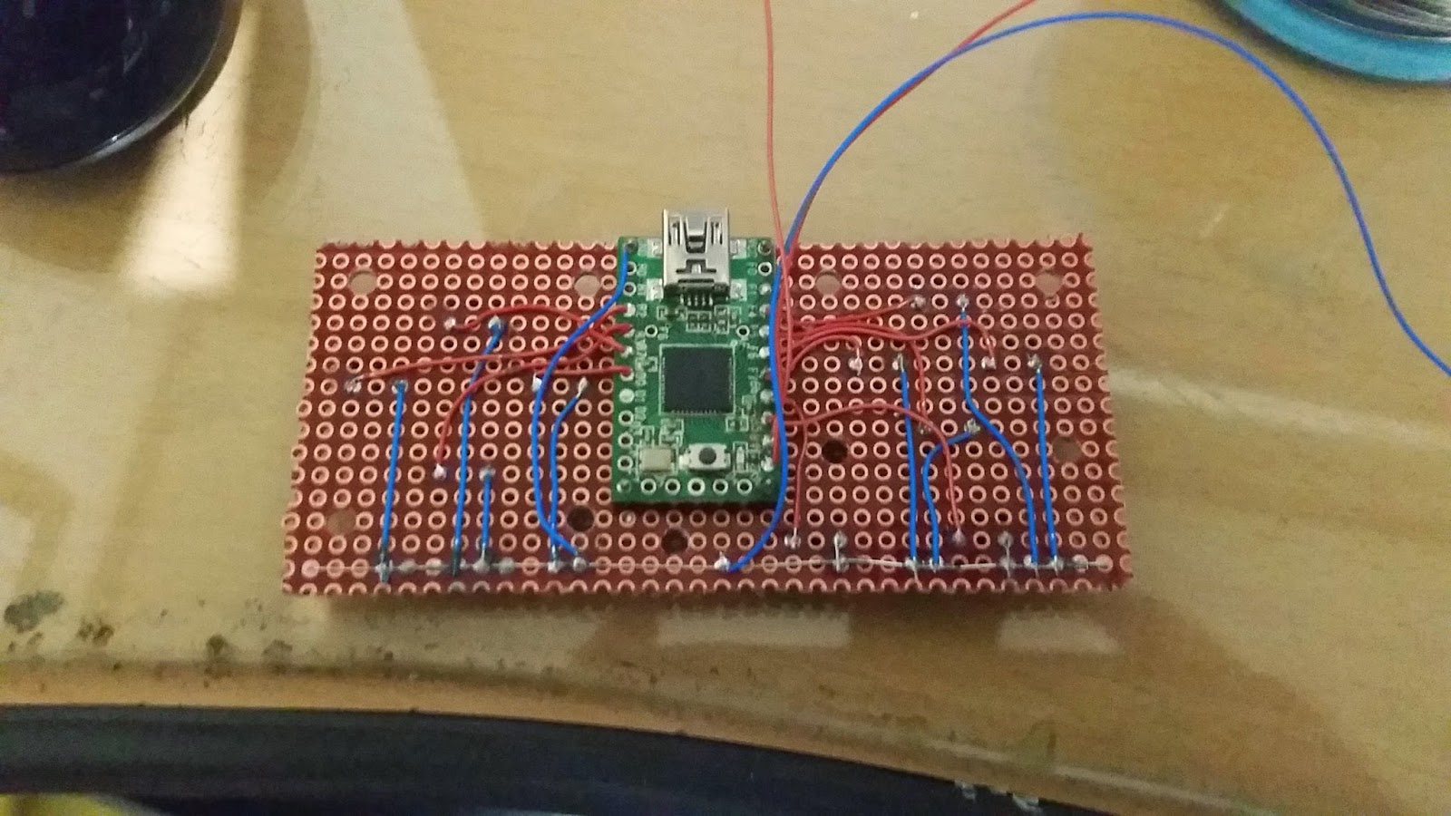
으로 인쇄되어 있는데, 사진처럼 s0 + 0, s1 + 0 땜질 되어 있으면 0 0 임,

NFC 리더와 라즈베리파이는 다음과 같이 연결한다.
NFC tx ---> Rpi pin10 (UART rx)
NFX rx ---> Rpi pin8 (UART tx)
송/수신이 바뀔경우 아래와 같이 nfc-poll 을 실행할 경우 에러가 발생한다.(nfc-poll은 Step 1 에서 실행 할 수 없음.)
pi@doorpi ~/libnfc-1.7.1/examples $ sudo ./nfc-poll
/home/pi/libnfc-1.7.1/examples/.libs/lt-nfc-poll uses libnfc 1.7.1
error libnfc.chip.pn53x Unexpected PN53x reply!
error libnfc.driver.pn532_uart pn53x_check_communication error
lt-nfc-poll: ERROR: Unable to open NFC device.
pinout 에 대한 자세한 정보는 google 에서 검색 해 보시라...
Step 2. 라즈베리파이 UART 통신 enable
기본설정으로 라즈베리파이의 UART는 시스템의 Serial console 용으로 설정되어 외부 장치의 입/출력을 받을 준비가 되어 있지 않다. 아래의 절차를 통해 외부 입/출력이 가능하도록 수정한다.
pi@doorpi ~ $ sudo raspi-config

8 Advanced Options 선택.

A8 Serial 선택.


<OK> <Finish>
Raspberry Pi 재부팅.
Step3. libnfc 컴파일
https://bintray.com/nfc-tools/sources/libnfc 에서
libnfc-1.7.1.tar.bz2 를 다운로드.
pi@doorpi ~ $ mkdir libnfc
pi@doorpi ~ $ cd libnfc/
pi@doorpi ~ $ cp libnfc-1.7.1.tar.bz2 ~/libnfc/
pi@doorpi ~ $ bzip2 -d libnfc-1.7.1.tar.bz2
pi@doorpi ~ $ tar -xvf libnfc-1.7.1.tar
libnfc-1.7.1/
libnfc-1.7.1/install-sh
libnfc-1.7.1/CMakeLists.txt
libnfc-1.7.1/aclocal.m4
libnfc-1.7.1/INSTALL
-- snip --
conf 디렉터리 만들고 conf 파일 복사.
pi@doorpi ~ $ mkdir -p /etc/nfc/devices.d
pi@doorpi ~ $ cd libnfc-1.7.1/
sudo cp contrib/libnfc/pn532_uart_on_rpi.conf.sample /etc/nfc/devices.d/pn532_uart_on_rpi.conf
sudo nano /etc/nfc/devices.d/pn532_uart_on_rpi.conf
줄 맨 마지막에 아래의 내용을 추가
allow_intrusive_scan = true
아래와 같이 된다.
pi@doorpi ~ $ cat /etc/nfc/devices.d/pn532_uart_on_rpi.conf
## Typical configuration file for PN532 device on R-Pi connected using UART
## Note: to use UART port on R-Pi, you have to disable linux serial console:
## http://learn.adafruit.com/adafruit-nfc-rfid-on-raspberry-pi/freeing-uart-on-the-pi
name = "PN532 board via UART"
connstring = pn532_uart:/dev/ttyAMA0
allow_intrusive_scan = true
라즈베리파이를 재부팅.
pi@doorpi / $ sudo reboot
pi@doorpi ~/libnfc-1.7.1 $ sh ./configure --with-drivers=pn532_uart --sysconfdir=/etc --prefix=/usr
fatal: Not a git repository (or any of the parent directories): .git
checking for a BSD-compatible install... /usr/bin/install -c
checking whether build environment is sane... yes
checking for a thread-safe mkdir -p... /bin/mkdir -p
checking for gawk... no
checking for mawk... mawk
checking whether make sets $(MAKE)... yes
checking for style of include used by make... GNU
--snip --
Selected drivers:
acr122_pcsc...... no
acr122_usb....... no
acr122s.......... no
arygon........... no
pn53x_usb........ no
pn532_uart....... yes
pn532_spi....... no
pn532_i2c........ no
pn532_uart 를 사용하도록 되었는지 확인.
pi@doorpi ~/libnfc-1.7.1 $ sudo make clean
Making clean in test
make[1]: Entering directory '/home/pi/libnfc-1.7.1/test'
test -z "" || rm -f
test -z "" || rm -f
rm -rf .libs _libs
test -z "" || rm -f
rm -f *.o--snip --
pi@doorpi ~/libnfc-1.7.1 $ sudo make install all
Making install in libnfc
make[1]: Entering directory '/home/pi/libnfc-1.7.1/libnfc'
Making install in chips
make[2]: Entering directory '/home/pi/libnfc-1.7.1/libnfc/chips'
CC libnfcchips_la-pn53x.lo
CCLD libnfcchips.la
make[3]: Entering directory '/home/pi/libnfc-1.7.1/libnfc/chips'--snip --
nfc-poll 을 실행 한 후 리더에 스마트 폰이나 nfc 를 접촉하면 데이터 가 수신된다.
pi@doorpi ~/libnfc-1.7.1 $ cd examples/
pi@doorpi ~/libnfc-1.7.1/examples $ ./nfc-poll
/home/pi/libnfc-1.7.1/examples/.libs/lt-nfc-poll uses libnfc 1.7.1
NFC reader: pn532_uart:/dev/ttyAMA0 opened
NFC device will poll during 30000 ms (20 pollings of 300 ms for 5 modulations)
ISO/IEC 14443A (106 kbps) target:
ATQA (SENS_RES): 00 04
UID (NFCID1): e3 28 ca de
SAK (SEL_RES): 08
nfc_initiator_target_is_present: Target Released
Waiting for card removing...done.
이제 nfc-poll을 샘플삼아 내게 맞는 코딩을 작성하면 되겠다.
#### PN532 uart for raspberry pi 3 (2016/07/24)
Raspberry pi 3 에서 /dev/AMA0 는 bluetooth 를 위해 사용되고. GPIO를 통한 uart는 /dev/serial0 으로 바뀌었다./boot/config.txt 의 맨 마지막 줄에 다음과 같은 라인 추가.
core_freq=250
enable_uart=1
라즈베리파이 재부팅
/etc/nfc/devices.d/pn532_uart_on_rpi.conf 파일내 uart port 변경
pi@raspberrypi:~/libnfc-1.7.1/examples $ cat /etc/nfc/devices.d/pn532_uart_on_rip.conf
## Typical configuration file for PN532 device on R-Pi connected using UART
## Note: to use UART port on R-Pi, you have to disable linux serial console:
## http://learn.adafruit.com/adafruit-nfc-rfid-on-raspberry-pi/freeing-uart-on-the-pi
allow_intrusive_scan=true
name = "PN532 board via UART"
connstring = pn532_uart:/dev/serial0
pi@raspberrypi:~/libnfc-1.7.1/examples $ ./nfc-poll
/home/pi/libnfc-1.7.1/examples/.libs/lt-nfc-poll uses libnfc 1.7.1
NFC reader: pn532_uart:/dev/serial0 opened
NFC device will poll during 30000 ms (20 pollings of 300 ms for 5 modulations)
ISO/IEC 14443A (106 kbps) target:
ATQA (SENS_RES): 00 04
UID (NFCID1): 83 b3 a6 ef
SAK (SEL_RES): 08
nfc_initiator_target_is_present: Target Released
Waiting for card removing...done.